On 20th and 21st November, the MAREWIND consortium met in the headquarters of Institute of Science and Innovation in Mechanical and Industrial Engineering (INEGI) in Porto (Portugal) to discuss the status of the project.
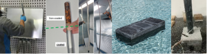
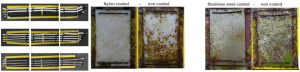
The MAREWIND consortium reviewed the work done and achievements reached until M36 (November 2023) on all the work packages. During the last months Koshkil, Lurederra and Tecnan have been working on the repair and maintenance activities. As a result, they have identified novel implementation strategies that have been successfully implemented on larger samples. For more than 8 months, the treated sample was exposed to outdoor conditions without exhibiting any signs of alteration. In contrast, the untreated sample displayed corrosion damage within the first week of exposure.
Lurederra has also been carrying out the drying and curing evaluation under different conditions of anticorrosion coating, in order to validate its application in different scenarios of humidity and temperature. Consequently, the coatings presented a great performance with more than 4,200 hours of corrosion resistance. Furthermore, Tecnan has confirmed the antifouling coating properties on real samples, demonstrating repellent effect, accomplished the challenge of upscaling the production of both anticorrosion and antifouling nanocoatings reaching 100L batches. In the same way, TWI has successfully manufactured 100 litres of antierosion/superhydrophobic paint, validating its scalability and completing the 3 coating prototypes envisaged. Following the validation of the prototype design, manufacturability, survival, and monitoring system with Fiber Optic (FO) sensors, CETMA proceeded to create two sensorised reinforcement meshes. These meshes had distinct configurations – one for the UHPC floating foundation prototypes and another for the AAC deep foundation prototype. During this period, ACCIONA has focused on UHPC prototypes design and manufacturing for its final goals: FO sensors response monitoring and UHPC durability performance in real environment, envisaged to be tested at Gijón Port. The MAREWIND project is reaching its concluding phase in November 2024. Therefore, full-scale tests are being implemented. EnerOcean has already conducted multiple real exposure experiments of anticorrosion coatings, demonstrating that samples coated by TECNAN outperform both uncoated and commercial ones, even with reduced thickness, as indicated by the results. The post-exposure tests indicates a robust corrosion resistance, displaying comparable results in both splash and atmospheric zones. Additionally, there are outstanding outcomes regarding the hardness and adherence of samples, both before and after exposure. Today, EireComposites is working on the validation testing of blade components and manufacture of prototypes. In this context, the full blade prototype production will be soon delivered including is corresponding coated fastening elements (TSF-TECNAN).Why did you join the MAREWIND project and what’s your role?
Our commitment to reach a cleaner and more sustainable future has brought us to participate in the MAREWIND project and support the development of innovative solutions that will enhance the durability and maintenance of renewable energy technologies.
Thanks to our overall expertise we are focusing our efforts on the challenges encountered by the materials exposed to the harsh conditions in offshore wind installations: durability and sustainability. Furthermore, as experts in computational science we are also contributing to the improvement of the design and development of materials.
What are your ambitions in contributing to the European Renewable energy targets?
At Idener, we believe that digital tools have an important role to play in the transition to a more sustainable future, particularly in achieving the European renewable energy targets. Our ambition is to leverage our expertise in applied computational science and research to develop innovative solutions that optimise the performance and cost-effectiveness of renewable energy systems. By integrating advanced modelling, simulation, and optimisation techniques, we aim to enhance the efficiency, reliability, and overall contribution of renewable energy sources, such as offshore wind, to the European energy landscape.
As experts in computational science, how do you apply your knowledge in the MAREWIND project’s development? Are you also applying it in other sectors?
Within the MAREWIND project, Idener is applying its knowledge in the development and implementation of predictive corrosion models specifically tailored for coated offshore infrastructures, always taking into account changing climatic conditions. While our focus in the MAREWIND project is on renewable energy, we also apply our computational science knowledge to other sectors such as industrial technologies, ICTs, biotechnology, and resource efficiency.
What factors do you consider when setting the predictive corrosion model?
When setting the predictive corrosion model for offshore infrastructures, we take into consideration factors such as the climatic conditions that the offshore facilities will be exposed to. This includes factors such as temperature, humidity, salt deposition, and other environmental variables. Furthermore, we consider the expected service life of the offshore infrastructure.
How do you see the future of the MAREWIND project?
We envision a promising future for the MAREWIND project. We believe that the project’s focus on developing advanced durable materials, recyclable solutions, and predictive corrosion models will greatly benefit the offshore wind energy sector.
By extending the service life of wind facilities and improving their performance, the project will contribute to the growth and expansion of the sector. We are confident that the project will have a lasting impact, supporting Europe’s renewable energy targets and reinforcing its position as a leader in the clean energy transition.
Read more about IDENER here.
Why did you join the MAREWIND project and what’s your role?
CETMA has always been involved in research activities related to the sustainability of materials, its areas of interest range from plastic/composite materials to building materials. The MAREWIND project addresses the problem of the durability of these materials and CETMA has fielded its expertise in this regard with the aim of strengthening and expanding them.
In MAREWIND project, CETMA will study cement-free and durable concretes for offshore foundation, a structural monitoring system based on fibreoptics to monitor the stress state of Fibre-reinforced plastic (FRP) reinforcing bars, recyclable resin for the production of wind blades and recycling techniques for composite materials (wind turbines at the end of their life).
As expert in materials engineering, what are your ambitions in contributing to the European Renewable energy targets?
CETMA’s ambition is to identify sustainable materials and solutions that can be used in the renewable energy sector. The wind energy sector, as well as the photovoltaic sector, still need supports, structures, infrastructures to be able to function and identify sustainable, durable and recyclable materials that would help make these interventions less impacting from an environmental point of view. On the concrete side, the ambition is to reduce reducing the CO2 footprint and costs of concrete without compromising its performance in terms of mechanical performance and durability, thanks also to the sensorised composite bars.
On the composite side, the work carried out aims to develop new sustainable solutions for the production of wind turbines of the future and to recycle wind turbines at the end of their life.
Besides innovation materials for the wind sector, is CETMA developing materials in other sectors? Are there similarities in the way these materials are developed? In MAREWIND, how has been the process to obtain new concrete materials?
CETMA has always carried out research and innovation activities in the field of advanced materials applied to several sectors such as aerospace, automotive, aeronautics and the construction sector. In all these applications, the approach consists in studying the reference materials and introducing innovation starting from the constituent elements and up to the production process. The common goal is environmental sustainability, weight reduction, performance increase or cost reduction.
The process to obtain the new AAM concrete for marine foundations starts from the required performance characteristics by formulating and testing AAM mixtures able to satisfy these requirements. The process involved developing a cement-free binder with high mechanical strength characteristics, then evaluating its behaviour after the addition of sand to obtain a mortar and the subsequent addition of coarse aggregates and high-density aggregates to develop the final concrete. Tests were performed for each of the formulated mixtures to identify the most promising one that was optimised.
How CETMA is contributing in implementing a more sustainable wind sector?
The solutions developed by CETMA aim at the use of waste materials from the metallurgical industry (slag and sludge) for the development of more durable cement-free concretes compared to traditional concretes; the use of sensorised FRP reinforcing bars also reduces or eliminates the risk of corrosion, extending the useful life of the components.
As far as wind turbines are concerned, however, the development of more sustainable, and recyclable polymeric matrices makes these elements more sustainable from an environmental point of view.
How do you see the future of the MAREWIND project?
The MAREWIND project represents an important starting point for wind energy. The solutions that are being developed will support the birth of a more sustainable new generation of more sustainable wind power plants. Some of the topics dealt with, if further explored, will become new commercial realities available to the designers of these systems.
Read more about CETMA here.
Why did you join the MAREWIND project and what’s your role?
MAREWIND project intends to provide solutions for developing advanced materials and nanotechnologies that will contribute to accelerating clean energy adoption for the energy transition within Europe. The overall concept of extended service life of wind-facilities is critical especially for renewable energies and this scope/goal fascinated TWI to join MAREWIND. Within our team, we manage work packages by internal technical help and contractual support.
As expert in innovative solutions for the inspection of both onshore and offshore wind turbines, what are your ambitions in contributing to the European renewable energy targets?
To achieve the European renewable energy targets, it is crucial to maximise the efficiency and reliability of wind turbines, both onshore and offshore. TWI will continue contributing towards renewable energy targets, via testing and evaluation of materials and components, service life-span performance, remote monitoring and inspection, artificial intelligence and machine learning, robotics and automation or in data integration and analytics.
What are the main solutions you are exploring to face challenges in the framework of the offshore wind industry?
Rain erosion poses significant challenges in the framework of the offshore wind industry. Offshore wind turbines are exposed to various environmental conditions, and rain erosion is a key factor that negatively affects their performance and lifespan and requires regular maintenance.
The impact of rain-erosion on wind turbines is centred on blade erosion, particularly at the leading edge. This leads to loss of efficiency, increased maintenance costs, safety concerns and increased downtime. In this context, these challenges are mitigated by blade coatings, regular inspections, improved blade design, maintenance strategies and by monitoring weather conditions.
In MAREWIND, what have been the main challenges to validate the testing of antierosion superhydrophobic and what you have achieved?
In MAREWIND, our focus is to improve life-expectancy of wind-turbine blades by improving blade coatings. The main challenges to validate the testing of antierosion superhydrophobic coatings were to design a system that not only provide external features of hydrophobicity but also provide a strong inter-layer adhesion to the glass-fibre epoxy substrates. The impact of rain droplets at high velocities generate high intensity shock waves that propagate from the surface through to the composite. These shockwaves can cause delamination of coatings and damage to the composite. To mitigate such damage a hybrid system of primer-layer, flexible inter-layer and hard-top layer is introduced. Through the application of the coatings by using industrial standard spray coating deposition method, TWI has demonstrated the property blend of repellency, abrasion resistance and erosion resistance.
How do you see the future of the MAREWIND project?
The future of MAREWIND project is very exciting. A lot of work has been undertaken and much data has been generated during the first 30 months of the project. Translation of initial results to field application will be key to developing innovative technical solutions that can be demonstrated and eventually adopted at industrial scale.
Read more about TWI here.
Era Baru Hiburan Game Online yang Lagi Naik Daun di 2026
Dunia hiburan digital sekarang udah beda jauh dibanding bos67 beberapa tahun lalu. Kalau dulu orang main game online cuma buat killing time pas lagi gabut, sekarang semuanya berubah jadi bagian dari gaya hidup modern. Tahun 2026 bisa dibilang jadi era di mana platform hiburan online berkembang makin liar, makin kreatif, dan makin bikin penasaran haha303. Banyak orang sekarang bukan cuma nyari permainan biasa, tapi juga sensasi, hiburan cepat, tampilan kece, dan pengalaman yang bikin nagih.Perkembangan Teknologi Membuat Semua Jadi Lebih Praktis
Perkembangan teknologi bikin semua akses jadi jauh lebih simpel hokihoki. Orang-orang nggak mau lagi ribet buka platform yang lemot, loading lama, atau tampilannya jadul kayak warnet tahun 2010. Sekarang user lebih suka sesuatu yang clean, cepat, responsif, dan enak dipakai baik lewat HP maupun desktop. Bahkan kebanyakan pemain zaman sekarang hokihoki.link lebih sering akses lewat smartphone karena lebih praktis dan bisa dimainkan kapan aja tanpa harus duduk depan komputer berjam-jam. Fenomena ini bikin banyak platform digital berlomba-lomba meningkatkan kualitas sistem mereka koko11. Kecepatan akses, desain modern, dan user interface yang friendly sekarang jadi prioritas utama. Kalau sebuah platform gagal mengikuti perkembangan tren digital, user biasanya langsung pindah ke tempat lain yang lebih nyaman dan lebih fresh koko188.Kenapa Mobile Gaming Jadi Favorit?
- Akses lebih cepat dan fleksibel
- Bisa dimainkan kapan saja
- Tampilan lebih modern dan ringan
- Tidak perlu perangkat mahal
- Lebih cocok untuk gaya hidup modern
Komunitas Online yang Semakin Aktif dan Viral
Fenomena game online modern juga makin ramai karena komunitas digital tumbuh super cepat koko288. Di media sosial, grup chat, forum online, sampai live streaming, obrolan soal permainan viral hampir nggak pernah berhenti. Ada aja topik baru tiap hari. Mulai dari game yang lagi hype, strategi unik, sampai cerita hoki yang bikin orang lain auto kepo. Hal-hal kayak gini bikin suasana komunitas koko303 jadi lebih hidup dan nggak monoton. Budaya nongkrong online sekarang juga makin kuat. Kalau dulu orang nongkrong di kafe https://koko303.cfd/ atau warung kopi, sekarang banyak yang nongkrong virtual sambil ngobrol di voice chat, live stream, atau grup komunitas. Mereka saling berbagi cerita, pengalaman unik, bahkan saling kasih rekomendasi game yang lagi rame dimainkan.Hal yang Membuat Komunitas Digital Semakin Besar
- Konten viral di media sosial
- Live streaming yang interaktif
- Forum diskusi yang aktif setiap hari
- Update game yang terus berkembang
- Rasa kebersamaan antar pemain
Gaya Bermain Modern yang Lebih Unik
Yang menarik, banyak pemain sekarang punya gaya main masing-masing koko33. Ada yang percaya sama timing tertentu, ada yang suka main santai sambil ngopi, ada juga yang punya “ritual hoki” sendiri sebelum mulai sesi permainan. Walaupun hasil akhir tetap bergantung pada keberuntungan dan sistem permainan, sensasi mencari momentum terbaik koko5000 jadi bagian yang bikin pengalaman terasa lebih seru. Banyak user juga mulai memperhatikan pola permainan dan strategi personal https://koko5000.link/. Walaupun semuanya tetap berbasis hiburan, beberapa pemain merasa punya ritme tertentu yang membuat pengalaman bermain jadi lebih nyaman dan menyenangkan.Tampilan Futuristik Jadi Daya Tarik Utama
Di tahun ini juga muncul tren baru di mana tampilan visual jadi salah satu faktor penting koko 5000. Banyak platform memakai desain futuristik, efek neon, animasi modern, dan nuansa cyber yang bikin pengalaman main terasa lebih premium. Buat generasi sekarang, first impression itu penting banget. Kalau tampilan awalnya aja udah keren, rasa penasaran user otomatis naik. Visual modern sekarang bukan cuma soal estetika, tapi juga bagian dari pengalaman pengguna secara keseluruhan kokogacor77. Animasi halus, warna yang elegan, dan efek visual yang immersive membuat pemain merasa lebih nyaman saat menjelajahi platform digital mami188.Elemen Visual yang Sedang Tren di 2026
- Nuansa cyber futuristic
- Animasi responsif
- Efek neon modern
- Tampilan minimalis premium
- Desain mobile-friendly
Kecepatan dan Kenyamanan Jadi Prioritas
Platform hiburan digital modern sekarang nggak cuma jual tampilan keren doang mega288. Mereka juga mulai fokus ke kenyamanan user secara keseluruhan. Mulai dari akses cepat, keamanan akun, transaksi lancar, sampai customer service yang aktif 24 jam jadi nilai plus tersendiri. Pemain zaman sekarang lebih kritis dan nggak gampang puas megawin188. Di sisi lain, perkembangan internet yang makin cepat bikin kualitas pengalaman bermain ikut naik drastis. Koneksi stabil memungkinkan animasi lebih halus, loading lebih ringan, dan gameplay terasa lebih responsif. Buat user, hal-hal kecil kayak gini ternyata sangat memengaruhi kenyamanan selama bermain.Permainan Modern Penuh Sensasi dan Kejutan
Salah satu alasan kenapa hiburan digital makin populer adalah karena sensasi unpredictablenya pulsa303. Nggak ada yang benar-benar tahu apa yang bakal terjadi dalam satu sesi permainan. Kadang biasa aja, kadang tiba-tiba muncul momen yang bikin jantung deg-degan. Nah, unsur kejutan inilah yang bikin banyak orang merasa pengalaman bermain jadi lebih hidup dan nggak membosankan. Selain hiburan, banyak user juga menikmati sisi kompetitif dari permainan online. Ada kepuasan tersendiri saat berhasil melewati tantangan, menemukan pola permainan favorit, atau mendapatkan momen yang jarang terjadi. Perasaan ini yang sering bikin pemain balik lagi karena ada sensasi pencapaian yang terasa personal.Alasan Banyak Orang Betah Bermain Online
- Gameplay yang tidak monoton
- Selalu ada kejutan baru
- Komunitas yang ramai
- Bisa dimainkan kapan saja
- Memberikan sensasi hiburan cepat
Media Sosial Membantu Tren Hiburan Digital Meledak
Media sosial punya pengaruh besar terhadap perkembangan hiburan digital saat ini. Konten viral tentang kemenangan fantastis, reaksi heboh streamer, atau cuplikan gameplay unik sering banget muncul di timeline orang-orang virtusplay. Dari situ rasa penasaran muncul, lalu makin banyak user baru yang ikut mencoba pengalaman serupa. Content creator juga punya peran besar dalam membentuk tren hiburan online modern. Banyak orang tertarik mencoba sesuatu setelah melihat review, live streaming, atau video singkat yang lewat di media sosial mereka.Teknologi AI Mulai Mengubah Pengalaman User
Industri hiburan online sekarang juga mulai memanfaatkan teknologi kecerdasan buatan untuk meningkatkan pengalaman user. Sistem rekomendasi modern bisa membaca kebiasaan pemain lalu menyarankan permainan yang sesuai dengan minat mereka. Jadi pengalaman terasa lebih personal dan nggak random. Teknologi seperti ini bikin user merasa lebih dimengerti. Mereka tidak perlu mencari terlalu lama karena sistem sudah otomatis menampilkan hiburan yang sesuai dengan preferensi masing-masing.Hiburan Digital Jadi Tempat Pelarian dari Rutinitas
Hal lain yang bikin dunia game online makin berkembang adalah karena adanya rasa “escape” dari rutinitas harian. Banyak orang menggunakan hiburan digital sebagai cara buat refreshing setelah aktivitas padat. Saat masuk ke dunia permainan, mereka bisa sejenak lupa sama tekanan kerjaan, tugas, atau drama kehidupan sehari-hari. Tahun 2026 juga jadi era di mana platform digital berlomba-lomba membangun komunitas loyal. Mereka sadar kalau user nggak cuma nyari permainan, tapi juga suasana dan kenyamanan. Karena itu banyak platform mulai menghadirkan event komunitas, fitur interaktif, sampai bonus loyalitas untuk menjaga hubungan dengan para pemain tetap aktif.Faktor yang Membuat Hiburan Digital Semakin Populer
- Mudah diakses kapan saja
- Tampilan modern dan interaktif
- Komunitas aktif dan ramai
- Gameplay penuh kejutan
- Teknologi yang terus berkembang
Masa Depan Hiburan Online Akan Semakin Canggih
Melihat perkembangan yang ada sekarang, masa depan hiburan online kemungkinan bakal jauh lebih canggih. Teknologi baru, desain visual yang makin realistis, dan fitur interaktif modern bakal terus bermunculan. Pengalaman bermain nantinya nggak cuma soal permainan itu sendiri, tapi juga soal bagaimana user merasakan atmosfer digital yang immersive dan penuh kejutan. Di tengah dunia yang serba cepat ini, hiburan online berhasil jadi salah satu tempat pelarian https://www.marewind.eu/news/rina-interview/ favorit banyak orang. Bukan cuma karena sensasi permainannya, tapi juga karena suasana modern, komunitas aktif, dan pengalaman seru yang terus berubah setiap waktu. Dunia digital sekarang bukan lagi sekadar tren sementara, melainkan sudah menjadi bagian besar dari budaya internet modern yang terus hidup dan berkembang. Dengan perkembangan teknologi yang semakin cepat, industri hiburan online diprediksi akan terus tumbuh dalam beberapa tahun ke depan. Pengalaman digital yang lebih realistis, interaksi sosial yang lebih luas, dan sistem yang semakin pintar akan membuat dunia hiburan online menjadi semakin menarik untuk diikuti oleh berbagai kalangan.As precursor of the MAREWIND project, what led you to take the road to set the consortium and what’s your current role?
LUREDERRA has previous activities and very promising results on anticorrosion and antifouling coatings. The offshore market is a challenging sector, but our coating technology advancements have enabled us to effectively address its demand within the MAREWIND project.
Furthermore, LUREDERRA has a great expertise in EU-funded projects both as coordinator and part of the consortium. These prior experiences have equipped us with the expertise to confidently lead the proposal MAREWIND “MAterials solutions for cost Reduction and Extended service life on WIND off-shore ” in the topic LC-NMBP-31-2020; Materials for off shore energy (IA).
What are your ambitions in contributing to the European renewable energy targets?
To contribute to the development of the next generation of large offshore wind energy, LUREDERRA has leveraged its expertise to offer solutions that address the current challenges associated with anticorrosion and antifouling coatings.
What were the main challenges when defining the requirements of new materials?
The primary challenges when defining the requirements of anticorrosion and antifouling coatings are closely related to the extremely harsh conditions encountered in offshore wind farms. In particular the main challenge that anticorrosion coatings are facing is the resistance to combine elements such as UV, temperature, and carrion. Moreover, antifouling coatings have to deal with the efficient fouling barrier with a biocide free coating.
And those related to monitoring and predictive?
When exploring the requirements of monitoring, the main challenges are based on the definition of accurate technologies and the accessibility to farms for testing purposes. But, when referring to the requirements of predictability, a significant challenge arises in the form of the high volume of experimental data required.
What are the main results you have achieved as partner in the MAREWIND project?
Within our activities, the anticorrosion coating developed has revealed no corrosion damage after more than 4200 hours in saline mist chamber and has been tested based on specific conditions from ISO 12944-9 (Protective paint systems and laboratory performance test methods for offshore and marine related structures).On the other hand, the antifouling coating samples are being tested in PLOCAN facilities (PLataforma Oceánica de CANarias) according to ASTM 3623 regulation and demonstrating good results after 6 months of full immersion.
How do you see the future of the MAREWIND project?
As coordinator of the MAREWIND project, LUREDERRA is convinced of the success of the project. The efforts and engagement of the consortium to develop the MAREWIND technologies will yield fruitful results.
Read more about Lurederra here.
Why did you join the MAREWIND project and what’s your role?
INEGI’s offshore strategy aims at increasing the useful life of materials and structure in offshore wind farms. In this framework, INEGI joined the MAREWIND project to work on a twofold objective stemming from research activities that obtained results at lower TRL levels. In this regard, the possibility to test solutions at higher TRL levels – activity where INEGI is leader – is of uttermost importance and will service to validate the developed technologies closer to the market.
On the one hand, within MAREWIND, INEGI is developing and implementing a Structural Health Monitoring (SHM) system for Condition-based Monitoring of structural components – such as the wind blades or the generator structure – based on full-field image monitoring systems and fibre-optics technologies. This SHM system is state-of-the art in several technological aspects such as the capability to perform structural integrity evaluation with Digital Image Correlation on rotating objects. However, these have never been brought to a high-level TRL as anticipated with the MAREWIND project. In this context, INEGI also tested the advanced Distributed Fibre Optics (DFO) systems extensively in laboratory premises, but these have seldom been demonstrated in large, environmental-relevant, high TRL instances.
On the other hand, INEGI is contributing to the development of effective anti-fouling and anti-corrosion coatings for offshore structural components benefiting from INEGI’s developments in Sea applications.
What are your ambitions in contributing to the European Renewable energy targets?
INEGI has been involved in the Renewables arena from its very start. The offshore energies domain has dominated a good part of INEGI’s past and future plans and strategy and through the years INEGI undertook innumerous activities in topics related to this domain. INEGI therefore has the ambition to be a relevant technology supply player in the Portuguese and European offshore renewables and looks at this aspect of sea economy as an important source of future projects and endeavours.
Preventive or planned maintenance is the most frequently applied maintenance strategy within the offshore industry. In this context, how are you contributing to improve the monitoring techniques?
INEGI’s strategic orientation regarding maintenance of industrial assets is based on the firm belief that while some operations are best served by preventive or planned maintenance, many other can be optimized by making use of predictive maintenance. Advanced monitoring systems developed through the years have had, in many cases, the exact goal of supporting the operation of that paradigm change in the businesses under focus. Offshore renewables is such a case. Robust monitoring systems able to anticipate failure can optimise the operation of the energy production assets and gradually change the attitude regarding maintenance operations. INEGI is set to be a part of this change and invests in monitoring R&D towards that goal.
What are the main factors to take into account when developing a monitoring system for offshore wind farms?
The development of structural health monitoring systems requires careful consideration of several crucial factors, such as the definition of parameters of assessment and the selection and placement of sensors which are always of the utmost importance. In particular, when designing monitoring systems for offshore environments, the demanding environmental conditions take centre stage, as the system must be able to withstand the harsh weather conditions prevalent in these environments. This is because this system can lead to corrosion and failures caused by humidity requiring a comprehensive design that accounts for the resilience of sensors and supporting electronic equipment.
Within MAREWIND, how are you going to implement the monitoring techniques in real scale?
Within MAREWIND, the implementation of monitoring techniques of blades at a real scale involves two key approaches. Firstly, INEGI will use full-field techniques by deploying cameras on drones. These drones will fly near the wind turbine structures, capturing visual data. In this context, INEGI will employ advanced vision algorithms to analyse this data and provide continuous monitoring of the structural integrity of the wind turbines.
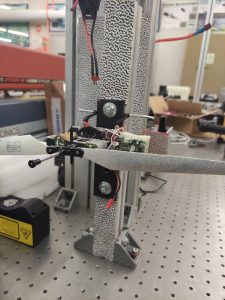
Secondly, we will incorporate fiber-optics technology-based monitoring systems into the blade prototypes developed within the project. The integration of the designed sensor networks into the blades will allow the capture of real-time data on their structural behaviour during the testing process. This data will provide valuable insights into the performance and integrity of the blades at a real scale.
The aim by combining these two approaches is that by applying comprehensive monitoring techniques, the structural integrity of wind turbine blades can be assessed under real conditions. In the future, the application of these techniques will help enhance maintenance practices, detect potential issues early on, and ensure the safe and efficient operation of wind energy systems.
How do you see the future of the MAREWIND project?
INEGI follows up close the developments in MAREWIND, with a special focus on condition-based monitoring but also contributing to the solutions for protective coatings and resilience increase of the overall offshore operation.
Portugal is a coastal EU country with many exploitable benefits from offshore renewables. In this context, the increase in operation’s reliability and effectiveness is tantamount to the market adhesion to offshore energy exploitation, becoming a critical component of the Portuguese strategy for the future. A large slice of that potential market investors is still considering the likely success of the investment. Therefore, the expected ROI and the results from MAREWIND may shift the balance towards a positive decision for many investors.
INEGI positions itself as one of the main RTO’s and service suppliers for that sector and we therefore embrace the future of MAREWIND as a decision game changer in our business.
Read more about INEGI here.
On 10th May the MAREWIND consortium met online to discuss the progress of the project.
During the last months the MAREWIND project has started the validation of technologies and materials in real environment. Throughout this natural step, the consortium will be able to verify whether the materials developed over the last two and a half years meet the expected requirements.
In this context, anticorrosion coatings are being tested for a duration of 8 months under real exposure conditions in the installations located in the Cantabrian Sea in the Bay of Biscay. Furthermore, validation testing of antifouling coatings has been performed with real samples provided by PLOCAN. Based on previous findings, it was observed that the coated samples exhibited a higher level of overall protection. To upscale this process, the consortium is testing it in 50 litre batches, but they plan to perform the test by using 100 litre batches in November 2023.
In terms of samples preparation method and optimisation of the third generation coatings for antierosion, the results obtained on abrasion performance testing and reduction in abrasion resistance were positive. As a result, TWI is currently planning to increase the softness of the interlayer. In addition, TWI is preparing the upscaling process.
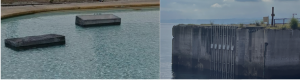
During this period, ACCIONA and CETMA have also prioritised the design of real-scale prototypes to conduct concrete mixture testing to characterize material’s durability, dynamic answer to waves and FRP (Fiber Reinforced Polymers) bars response. To mitigate cracking and manufacturing issues, steel reinforcement will be combined with the FRP sensorised rebars. On the other hand, to prevent water intrusion, ACCIONA will implement water tightness tests. To facilitate this, these samples will be located in Gijon’s Harbour facilities where 2-3 prototypes will be executed.
Eire Composite has also been working on the blade component’s testing and they are planning a small demonstration testing in June 2023. In this framework, CETMA has been working on the multi-scale numerical models and development of infusion strategies to help incorporate recyclable resins in wind turbine blade manufacturing. Additionally, INEGI is responsible for the fiber optic structural health monitoring (SHM) system for composite wind blade component testing.
In the upcoming months, the consortium will demonstrate the technologies developed by the project in relevant environments located in Canary Island/ Atlantic Ocean; Bay of Biscay/Cantabrian sea and English Channel (La Rance Site- France). Moreover, the environmental, economic and social analyses through Life Cycle Assessment (LCA) methodology performed by RINA-C will result in preliminary outcomes about new products performances.
The 17th E-LASS event held in Las Palmas (Spain) on the 3rd of May in was organised in collaboration with the FibreGY project.
The event provided a platform for MAREWIND and Carbo4Power projects to showcase their current status and share their latest results. Furthremore, E-LASS offered a valuable opportunity for knowledge exchange and dissemination.
During the event, EnerOcean presented the MAREWIND project. Key stakeholders expressed a notable interest in composites developed by the project, in particular those utilised in blades. Stakeholders also engaged in discussions about the recycling process applied by MAREWIND.
During the last months, the MAREWIND project has made great strides towards the validation of the developed samples. At present, the natural step is the validation in a real environment where formal controlled testing will be performed to ensure that the materials developed satisfy the expected requirements.
The consortium has started the work in real exposure and also with samples with real materials and morphologies, enabling relevant validation.
On the one hand, for bigger pieces, TECNAN has defined key parameters – such as flow rate, speed or distance – of spray gun application, and characterised the resulting samples with the aim to compare its properties versus the ones previously validated in the laboratory. Several application tests were carried out in order to adapt the procedure to complex and more realistic morphologies. More in detail, real pieces of mooring lines and inter array cables have been coated with the antifouling solution via spray gun, maintaining all the expected repellence properties, as in previous tests. The anticorrosion coating was also applied on samples around 1m2 and with curved and complex geometries with no imperfections observed. Besides, TECNAN has optimised strategies for removing the excess of product and curing conditions for real fastening elements regarding dip-coating application.
On the other hand, TWI for its side is improving the application of the superhydrophobic coating for blades for improved control and for having higher resistance to mechanical impact.
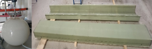
Additionally, as advanced concrete-based materials concerned, ACCIONA has made preliminary UHPC floating prototypes, focused on the relevant scale prototype design that will be tested in more realistic environments such as wave basin for offshore application studies (EUMER facilities), at the same time, real exposure durability testing will be performed at ACCIONA Habour demo-site. Furthermore, for the Alkali Activated Concretes (AAC), CETMA carried out a small-scale prototype with a complex geometry to evaluate the ability of the AAC to flow within the mould. They have also designed the final prototype indicating the number and position of SMART reinforcing rebars.
Advances concerning the blade prototype, imply that EIRE has been working on the validation demonstrator, testing the 5m wind blade spar box, as representative section of the main structural component of the 13 m blade.
As part of the validation activities, final optimisations of the selected formulations are being carried out in order to maximise the properties of the novel solutions developed.
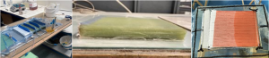
More in detail, TWI has started the optimisation of the best performing coating formulation, working on the 3rd generation of antierosion coatings adjustment. After several tests, TWI has adjusted the level of functionalized microparticles in the formulation, showing an increased wear resistance of the coating. For the reinforced composites formulations for blades, the contemplated strategies by TWI and CETMA, are progressing properly. Respecting the work of TWI, the final material test campaign for GF/epoxy-SiO2 as the new blade material was completed. The results are compared with conventional GF/epoxy, showing that the modified epoxy-SiO2 resin outperforms the conventional epoxy resin in the majority of property tests. CETMA for its side, is working on the infusion process of the TPR (thermoplastic reactive resin), as a new recyclable resins. The results of testing campaign for GF/TPR as the new blade material, has showed that properties of recyclable composite are comparable with conventional GF/epoxy laminates. They have defined the final composition, layup and geometry of the full TPR demonstrator, and as regards TPR matrix, CETMA has selected a specific recyclable resin to be used in scale up activities with low exothermic properties to produce large parts with thick sections.
The scale-up of formulations includes the progress regarding liquid nanocoating production as well as novel concrete or composite fabrication.
On the one hand, production of the anticorrosion and antifouling coatings started with first batches of 20 liters with suitable results, having the focus on the 100 liters target of production. The spray gun application and the monitorization of the key parameters (viscosity, particle size…) showed that the larger batches have the same tendency as the product made at laboratory scale. As a result, TECNAN will produce larger batches following the same parameters. In addition, INL is producing the self-healing active material for the anticorrosion system, and studying what is the most suitable format for the scalability.
Also, the preparation of pilot batches of SiO2 mixed with epoxy infusion resin (epoxy-SiO2) has already started by TWI side, in order to supply EIRE for the production of the new blade reinforced composites
.
After having performed all laboratory tests, the MAREWIND project is currently gradually moving to a real environment.
Currently, TECNAN is testing the bigger pieces in saline mist chamber before preparing the ones to be exposed to real conditions. Specific and bigger samples coated with the anticorrosion system are envisaged to be tested by ENEROCEAN in the upcoming months in real marine environment using TECNALIA’s HarshLab floating laboratory. On the other hand, ENEROCEAN is currently testing the antifouling coatings on flat panels, both partially submerged and in total immersion, as well as on real samples (moorings and cables) in real marine environment. These antifouling coatings tests are being performed at the Oceanic Platform of the Canary Islands (PLOCAN) facilities.
- Find more news here.
- Find more results here.
- Meet the consortium here.
- Follow us on LinkedIn and Twitter, and do not forget to subscribe to our newsletter here.
On 16th and 17th November, the MAREWIND consortium met in the headquarters of Lurederra Centro Tecnológico in Los Arcos (Navarra, Spain) to discuss the 2-year progress of the project.
The first day, the meeting started with the review of the work done and the achievements reached so far on the activities related to the predictive modelling and the SHM tools for preventive maintenance of wind energy. The discussion continued with the latest updates on the technology validation and the manufacturing activities performed during the last months, including upscaling of nanocoating formulations, the generation of floating concrete prototypes and advanced composite testing among others. To wrap the first day of the meeting, the last topic addressed the preparatory actions for the future demonstration of the technologies in relevant environments.
The second day was dedicated to the presentation of the upcoming steps in the technical validation of the results such as the baseline for LCA analysis. Then, the meeting followed by a summary of all the communication and dissemination results achieved from the beginning of the project. To conclude the meeting, the consortium presented the next steps which will be followed to face the upcoming exploitation and standardisation challenges.
Next stepsThe consortium is preparing its fourth newsletter. Stay tuned for more details about the progress achieved so far.
You can subscribe for the latest MAREWIND news and events, here.